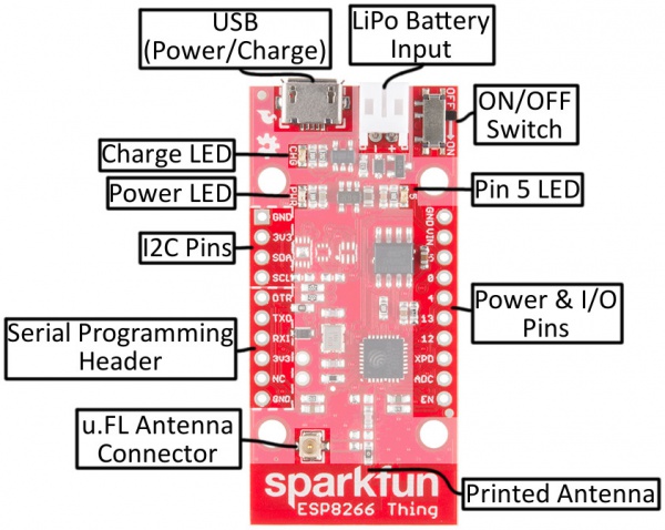
I have started testing the ESP8266 as an inexpensive WiFi enabled IoT device platform. I will added specific how-to notes later but wanted to capture a few items from my initial experiments.

I started with the Sparkfun Thing, which is a nice ESP8266 dev board that supports integrated LiPo battery management. They have a nice Hookup Guide to get you started. My use case is a very simple IoT type device that will send data to a cloud service that I have developed. The cloud service will aggregate the data from multiple personal IoT devices for a user. These devices will generally be powered via LiPo battery when in use for interaction and placed in a charging tray when not in interactive use. The devices are always active but have special meaning when in interactive use.
These constraints mean that battery life is a critical factor, but I do not need days, months, or years of battery life. The ESP8266 is a fairly power hungry device, especially when transmitting data, but it does have some power management features, most notably deep sleep.
Notes from my initial experiments:
The Kit
I used the Sparkfun Thing, FTDIBreakout for uploading code, and LiPo battery.
Setup
An easy way to get code running is to use the Arduino Addon that lets you leverage the Arduino libraries in programming the ESP8266. An alternative I will try in the future is the Lua based firmware.
When using the FTDI to program the board take note that GPIO0 is used to set the run mode of the firmware. 3.3V puts it in run mode and 0V puts it in program mode (bootloader). This is easy to miss in the instructions, so be sure to connect the 0 pin to ground when you wish to upload the code from the Arduino IDE.
Power Management
To use the deep sleep mode on the Sparkfun Thing you must connect XPD to DTR. Sparkfun connected DTR to RST on the Thing so a short negative voltage will reset the device. When in deep sleep most system services are powered off, but the RTC and timer interrupt remains active for the purpose of waking the device from sleep. This is handled by the firmware once these pins are connected, however this means you will have to remove the FTDI programmer to test the deep-sleep mode.
The deepsleep() call looks a lot like a delayMicroseconds() call, simply pass it the number of microseconds before it should wake up again. In deep sleep mode, the ESP8266 hits about 60 µA of power draw, down from its average of around 75mA, and the 200mA used while transmitting.
It should be possible to connect a button or some other independent sensor as an alternative to a timer based wakeup, so the device can be awaken by a button press or some physical world event.
ESP.deepSleep(1000000); //sleep for 1 second
Saving State
Unlike a call to delay() or delayMicroseconds(), the deepsleep() function actually causes the device to power down everything except the RTC and related services. Wake is essentially a device reboot and previous state is not maintained. This means any state will need to be stored in the ESP8266 EEPROM. For this there is an EEPROM library and EEPROM.get()
       //some struct for saved object
       struct BackupObj{
         int setting;
         int data;
       };

       //write
       int eeAddress = 0;
       EEPROM.begin(4096);  //set up memory allocation
       EEPROM.put( eeAddress, backupObj );
       EEPROM.commit();
       EEPROM.end();

       //read
       int eeAddress = 0;
       EEPROM.begin(4096);
       EEPROM.get( eeAddress, backupObj );
       EEPROM.end();
Adding Components
The device works well for I2C, in my case I tested with an MPU-6050.
       #include <Wire.h>

       void setup() {
         // ... other setup code
         Wire.begin();
         Wire.beginTransmission(MPU);
         Wire.write(0x6B);  // PWR_MGMT_1 register
         Wire.write(0);     // set to zero (wakes up the MPU-6050)
         Wire.endTransmission(true);
       }

       // using arduino's loop mechanism
       void loop(){
         // ... other loop code
         Wire.beginTransmission(MPU);
         Wire.write(0x3B);  // starting with register 0x3B (ACCEL_XOUT_H)
         Wire.endTransmission(false);
         Wire.requestFrom(MPU,14,true);
         AcX=Wire.read()<<8|Wire.read();
         AcY=Wire.read()<<8|Wire.read();
         AcZ=Wire.read()<<8|Wire.read();
         // ... other loop code
       }
I tested using GPIO with a piezo used as a speaker. The Speaker is capable of playing simple notes using frequency of note mapped to cycles of sound and delay.
       #define NOTE_C5  523 //middle C
       #define NOTE_D5  587

       const int SPEAKER_PIN = 5;

       void playNote(int targetPin, long frequency, long length) {
         long delay = 1000000 / frequency / 2;
         long cycles = frequency * length / 1000;
         for (long i = 0; i < cycle; i++) {
           digitalWrite(targetPin, HIGH);
           delayMicroseconds(delay);
           digitalWrite(targetPin, LOW);
           delayMicroseconds(delay);
         }
       }

       long noteDuration = 500;
       long frequency = NOTE_C5;

       playNote(SPEAKER_PIN, frequency, noteDuration);
I tested analog sensor input in the form of a second piezo connected to the ADC pin as a knock sensor. ADC is the only analog input pin on this device.
       const int KNOCK_SENSOR = A0;
       const int KNOCK_THRESHOLD = 70;

       sensorReading = analogRead(KNOCK_SENSOR);
       if (sensorReading >= KNOCK_THRESHOLD) {
         long noteDuration = 500;
         long frequency = NOTE_E5;
         playNode(SPEAKER_PIN, frequency, noteDuration);
       }
Finally there were enough pins remaining to hookup an RGB LED breakout. I added this test using the RGB Tools Lib.
       #include <RGBTools.h>

       const int RED_PIN = 4;
       const int GREEN_PIN = 12;
       const int BLUE_PIN = 13;

       // set the RGB pins - here I used pins 4, 13, and 12
       // use RGBTools rgb(4,13,12, COMMON_CATHODE); if using a cathode RGB
       RGBTools rgb(4,13,12);

       //set a nice red
       rgb.setColor(174,10,0);
Conclusion
This was a quick run through to test some of the feature of the device, but even with a few sensors/actuators and a simple setup there is a nice combination of status and interaction feedback that can be performed with a simple and relatively inexpensive device. The Sparkfun Thing retails for around $15 right now but the Huzzah is under $10, and others can be found closer to $5.